


Steps to Successful Installation of Vertical Circulating Water Pumps
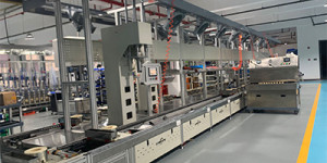
The power generation industry uses high-flow, low-head vertical pumps for circulating water in both fossil and nuclear power plants. Many of these plants are approaching 40 years old and require equipment refurbishment or component replacement. One specific component that has been a major topic of discussion is the circulating water pump.
Proper installation begins with the sole plate, which is the foundation for the pump. A poorly installed foundation will result in premature failure. Prior to installation, the bottom of the sole plate should be grit-blasted to a white metal finish and painted with epoxy primer then installed flat and level within 0.002 inches overall using leveling bolts. Allow a minimum 3 to 6 inches of clearance between the concrete intake structure and the sole plate for epoxy grout.
Steps for Successful Installation
- Sole plate must be flat and level within 0.002 inches. Use precision straight-edge, machinist level and feeler gauge.
- Motor stand (discharge head) must be flat and level within 0.002 inches (two places) between the motor stand and sole plate and the motor stand and motor.Use the same procedure as step one.
- Stuffing box should be concentric to motor stand.
- Check for soft foot motor stand to sole plate using dial indicator. This should require minimal shimming.
- Motor-to-motor mounting face should be flat within 0.002 inches. The motor shaft should be at a 90-degree angle to the mounting surface (see Figure 2).
- Ensure minimal shimming between the motor stand and motor (if Steps 1 through 5 were followed). Check for soft foot and torque to specification.
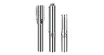
- Use a strong arm lift pump shaft to allow the rotating element (shaft/impeller) to center itself relative to stationary components, and allow installation of spacer blocks to retain centralization.
- Use precision spacer blocks to center pump shaft in stuffing box; offset alignment only. Release strong back.
- Using dial indicator, check for concentricity and parallelism at coupling faces. In some cases, it may be necessary to move stuffing box to achieve concentricity.
- Using laser alignment, align motor shaft to pump shaft.
- With alignment equipment installed, connect discharge piping while periodically checking alignment.